
 EN
EN
Quick Links
Drive wheels, follower wheels, and guide wheels serve fundamentally different mechanical purposes on any AGV (Automated Guided Vehicle). They cannot be selected using the same criteria, nor can they be swapped between positions without causing performance degradation, premature wear, or safety issues.
This guide explains the mechanical design differences between the three wheel types, provides parameter comparison tables across four dimensions (mechanical loading, tread compound selection, bearing configuration, and common failure modes), and outlines a practical 6-step selection workflow for AGV designers and procurement engineers.
Key takeaways: (1) Drive wheels need high-friction, high-wear-resistance tread compounds (~93 Shore A) with robust bearing assemblies. (2) Follower wheels prioritize low rolling resistance and floor protection (75-85 Shore A). (3) Guide wheels require lateral stiffness and precision mounting (85-93 Shore A). (4) All three wheel types should be selected in sequence — drive wheel first, then follower and guide wheels matched to the drive wheel baseline.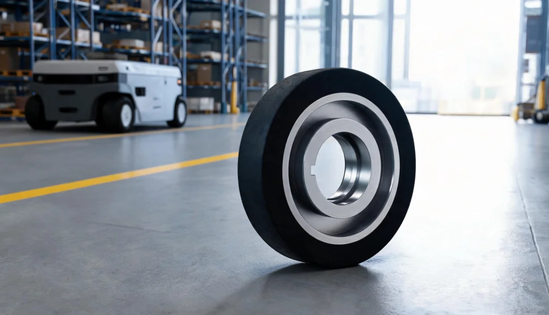
A common misconception in AGV maintenance and spare parts procurement is that drive wheels, follower wheels, and guide wheels "look similar enough to be interchangeable." In practice, swapping them between positions leads to a cascade of problems: drive wheel slippage, accelerated follower wheel wear, guide wheel tracking errors, and ultimately degraded AGV positioning accuracy.
The reason starts with the fundamental mechanical mission of each wheel type:
• Drive wheel — The power output end. Its job is to convert motor torque into horizontal tractive force that moves the AGV.
• Follower wheel — The load support end. Its job is to roll freely while bearing the vehicle's weight distribution.
• Guide wheel — The directional control end. Its job is to resist lateral forces and maintain the AGV's travel trajectory.
These three entirely different mechanical roles dictate fundamentally different design choices in tread compound, hardness, wheel diameter, bearing type, and mounting method. Understanding these differences is the prerequisite for correct selection, efficient spare parts management, and reliable AGV operation.
The drive wheel is the only wheel on an AGV that directly participates in power transmission. It must simultaneously bear vertical load (the portion of vehicle weight distributed to that wheel) and convert motor torque into horizontal tractive force. This creates a static friction pair between the tread surface and the floor. If the coefficient of static friction is insufficient, slippage occurs.
The maximum tractive force F follows the formula F = μN, where N is the normal load on the wheel and μ is the coefficient of friction. This means that if an AGV's payload increases by 20%, but the drive wheel's friction coefficient remains unchanged, slippage may occur under certain limit conditions. This is why industry practice recommends a minimum 30% load redundancy margin in AGV drive wheel selection.
Drive wheel tread compounds must strike a balance between grip and wear life. Higher friction means stronger tractive force, but excessively high friction often accelerates tread wear. In practice, AGV drive wheels commonly use polyurethane tread compounds around 93 Shore A — a hardness level that delivers sufficient traction while maintaining acceptable wear life under frequent start-stop cycles.
The Eamflex 93A tread system, developed specifically for drive wheel applications, demonstrates consistent performance under high-load, frequent start-stop AGV operations. This compound undergoes quality testing per DIN 53516 for abrasion resistance, with moderate rebound characteristics that allow it to output sufficient traction on common industrial floors (epoxy, concrete, steel plates) without premature failure from excessive friction. In a Mercedes-Benz automotive production line application, Eamflex-equipped drive wheels have operated for 48 consecutive months with zero quality-related returns.
Drive wheel hubs are typically made of cast iron or steel to withstand significant torque transmission. For bearing selection, drive wheels commonly use tapered roller bearings or deep groove ball bearings combined with thrust bearings to handle both radial loads and axial thrust. The GEFA and GEJA series heavy-duty drive wheels undergo precision machining on the hub, with coaxiality controlled within 0.05 mm to ensure rotational stability at operating speeds. When selecting bearings, Hanke's engineering team matches the bearing type and clearance class to the AGV's actual load parameters — including tare weight, rated payload, start-stop frequency, and turning radius.
The most frequent drive wheel failure modes include uneven tread wear, slippage, and debonding (tread separation from the hub). Uneven wear is typically caused by inaccurate AGV chassis alignment or a wheel axis that is not parallel to the travel direction. Slippage relates to overloading or insufficient tread hardness for the floor conditions. Debonding is directly linked to the bonding interface quality, specifically the blasting and adhesive application processes. In Hanke's manufacturing system, the blasting process follows the C-04 Blasting Work Standard, achieving surface roughness of Ra 25-50 μm and cleanliness of Sa2.5 grade — these are the quality foundations for reliable metal-to-polyurethane bonding.
Follower wheels do not participate in power delivery. Their motion is entirely passive, driven by the AGV's drive wheels. The forces on a follower wheel are primarily vertical load (the vehicle weight distributed to that position) and rolling resistance from passive rotation. Compared to drive wheels, follower wheel operating conditions are milder — no torque shock, no start-stop sliding. Yet precisely because of this, follower wheels are often the most overlooked component in AGV wheel system design.
This neglect leads to real problems. Excessive rolling resistance increases overall energy consumption and reduces battery range. An overly hard tread may leave marks or scratches on epoxy flooring. Incorrect bearing selection can cause wheel binding, leading to AGV tracking deviation. While these issues are not as immediately visible as drive wheel slippage, they significantly degrade AGV system efficiency and reliability over time.
Follower wheel tread requirements are essentially the opposite of drive wheels. Follower wheels need low rolling resistance and good floor protection rather than high friction. In practice, follower wheel polyurethane tread hardness is typically 75-85 Shore A — noticeably softer than drive wheels. This softer tread absorbs vibration, reduces noise, and minimizes scuffing on epoxy floor surfaces.
The Saxflex 75A tread system is designed for exactly these operating conditions. Its formulation prioritizes floor friendliness, making it well-suited for cleanrooms, cold storage warehouses, and other environments where floor surface protection is critical. In a KONE Elevator AGV follower wheel application, Saxflex 75A tread showed no visible marking on epoxy flooring after continuous operation, while maintaining low rolling noise levels. The VSA and VSB series follower wheels from Hanke are primarily equipped with Saxflex tread, available in different load ratings for floor-protection-oriented applications.
Follower wheel bearings are typically deep groove ball bearings, since follower wheels primarily carry radial loads with minimal axial force. In some low-cost designs, follower wheels use plain bushings (bronze or PTFE) instead of rolling-element bearings — this reduces cost and maintenance complexity but significantly increases rolling resistance. For AGVs that require manual pushing or frequent direction changes, designs with rolling-element bearings are recommended to minimize operating resistance.
This counterintuitive phenomenon occurs frequently in AGV field operations. The drive wheel bears higher mechanical stress in theory, yet maintenance records often show follower wheels failing first. Three root causes explain this: (1) During AGV turns, follower wheels experience lateral scrubbing — the wheel is forced sideways rather than rolling purely forward. (2) Follower wheel treads are intentionally softer (for floor protection), which naturally increases wear rate under scrubbing conditions. (3) Bearing binding in the follower wheel causes the tread to drag across the floor instead of rolling cleanly. The solution is to select follower wheel hardness appropriate to the actual turning frequency of the AGV route, and to inspect bearing condition at regular intervals.
The guide wheel has the most unusual loading profile among the three wheel types. It must bear a portion of vertical load while continuously resisting lateral forces — generated by centrifugal force during AGV turns, floor unevenness, and the transverse correction torque from the navigation system during path correction. The lateral stiffness of the guide wheel directly determines the AGV's straight-line stability and cornering tracking accuracy.
Guide wheels are typically mounted on the sides or diagonal corners of the AGV chassis, with their axis at a specific angle relative to the drive wheel axis (commonly tilted to create a contact angle with the floor). This tilted mounting design generates a continuous lateral positioning force as the AGV moves forward, adapted from proven industrial rail vehicle technology and widely applied in AGV design.
Guide wheel tread hardness falls between drive wheels and follower wheels, typically 85-93 Shore A. Too soft — excessive deformation under lateral force, compromising positioning accuracy. Too hard — increased impact transmission, raising noise and vibration levels. Guide wheels are often narrower than drive and follower wheels, a design trade-off that improves lateral stiffness within limited installation space while maintaining vibration damping characteristics. The HEB and HEC series guide wheels are designed for balanced lateral load capacity and rolling stability, using precision deep groove ball bearings with lateral retention structures to maintain positioning reliability under continuous side loading.
The mounting bracket for guide wheels is another critical design point. Because guide wheels experience continuous lateral forces, any loosening of mounting bolts or insufficient bracket rigidity causes the guide wheel contact angle to drift. This manifests as "snaking" during straight-line AGV travel — a common issue during AGV commissioning that is often traced back to guide wheel mounting integrity.
Guide wheel failures tend to be gradual rather than sudden, making them harder to detect than drive wheel slippage or follower wheel binding. Early-stage indicators include subtle S-shaped oscillation during straight-line travel. Mid-stage symptoms include uneven wheel speed between inner and outer sides during turns. Late-stage problems involve severe uneven tread wear or even wheel detachment. Lateral uneven wear is the hallmark failure mode of guide wheels — the continuous side load causes one side of the tread to wear significantly faster than the other. Regular inspection of guide wheel tread evenness is a critical maintenance item, with inspection frequency depending on the AGV's average daily operating distance and floor conditions.
The following four tables compare the three wheel types across mechanical, tread compound, bearing, and failure dimensions.
Parameter | Drive Wheel | Follower Wheel | Guide Wheel |
Primary load type | Traction + vertical load | Vertical load only | Lateral + vertical load |
Single wheel capacity | 500-3000 kg (heavy duty) | 200-1500 kg | 100-800 kg |
Friction requirement | High (≥0.5, needs grip) | Low (≤0.3, reduce drag) | Medium (0.3-0.5) |
Starting torque | High (motor-driven) | Low (passive rolling) | Medium (lateral preload) |
Lateral stiffness | Medium | Low | High (critical parameter) |
Dimension | Drive Wheel | Follower Wheel | Guide Wheel |
Hardness range | 93 Shore A | 75-85 Shore A | 85-93 Shore A |
Recommended system | Eamflex 93A (high wear resistance) | Saxflex 75A (floor protection) | Eamflex 93A or custom medium hardness |
DIN 53516 abrasion | Low (high wear resistance) | Medium (protection priority) | Medium-low (balance) |
Rebound rate | Moderate | Higher | Moderate |
Typical applications | Heavy-load AGV, frequent start-stop | Cleanrooms, cold storage | High-precision navigation AGV |
Configuration | Drive Wheel | Follower Wheel | Guide Wheel |
Bearing type | Tapered roller / Deep groove + thrust | Deep groove ball | Deep groove ball + lateral retention |
Clearance class | C3 (thermal expansion allowance) | Normal | Normal or C3 |
Lubrication | Grease packed | Grease / self-lubricating bushing | Grease packed |
Axial retention | Lock nut + retaining ring | Circlip | Lock nut + lock washer |
Inspection interval | 3-6 months | 6-12 months | 3 months (lateral load effect) |
Failure Mode | Drive Wheel | Follower Wheel | Guide Wheel |
Uneven tread wear | One-side wear → alignment issue | Center wear → overloading | Shoulder wear → lateral force |
Slippage / skidding | Overloading / insufficient friction | Bearing binding → dragging | Insufficient lateral force → wandering |
Debonding / tread separation | Bonding process / overload condition | Rare | Lateral impact induced |
Abnormal noise | Hard tread / floor contamination | Insufficient bearing lubrication | Loose mount / angle drift |
Overheating | Continuous high-load operation | Bearing failure | Lateral overload |
In the wheel system design for three-wheel or four-wheel AGVs, the logical selection sequence is: drive wheel → follower wheel → guide wheel. The drive wheel's core parameters (diameter, tread hardness, load rating) establish the AGV's power baseline, and all follower and guide wheel parameters must match against this baseline.
For example, if the drive wheel is a 300 mm diameter Eamflex 93A heavy-duty wheel, the follower wheel diameter should typically be 60%-80% of the drive wheel diameter (180-240 mm). This maintains consistent ground clearance while avoiding interference during turns that would occur if the follower wheel were too large.
Diameter matching is a detail that is easy to overlook. If the follower wheel is significantly larger than the drive wheel, when the AGV traverses uneven ground, the follower wheel may contact a raised surface before the drive wheel, temporarily lifting the drive wheel and losing traction. Conversely, if the follower wheel is too small, it may get stuck in floor gaps or rail joints. A common industry rule is follower wheel diameter at 60%-80% of drive wheel diameter, with the guide wheel slightly smaller than the follower wheel. This ratio is not fixed; it must be adjusted based on the AGV chassis structure and suspension design.
On the same AGV, the three wheel types can use different tread systems — they do not need to be uniform. A drive wheel with Eamflex 93A for traction, follower wheels with Saxflex 75A for floor protection, and guide wheels with a medium-hardness compound for directional precision — this is a valid differentiated configuration. However, if floor conditions change significantly (for example, an AGV moves from an epoxy workshop floor to a concrete warehouse), the tread match across all three wheel types should be reassessed.
In Hanke's project practice, a "one-AGV-one-solution" approach is commonly applied: tailor the tread system and structural parameters of drive, follower, and guide wheels to each AGV's specific load profile, floor type, steering method, and navigation accuracy requirements. This integrated wheel matching model has been deployed in production line AGV projects for Geely Automobile and Changan Automobile.
For AGV designers and procurement engineers, the following simplified workflow covers the key decision points:
Step 1: Determine the AGV's tare weight, rated payload, and maximum travel speed. These parameters define the tractive force the drive wheels must deliver and establish the minimum load rating for all wheels.
Step 2: Based on floor type (epoxy, concrete, steel plate, tile), select the drive wheel tread hardness. Start the evaluation at 93 Shore A. The smoother the floor, the lower the available friction coefficient and the higher the demands on tread grip.
Step 3: Based on chassis layout, determine the wheel diameter combination. Select the drive wheel first, then match follower and guide wheel diameters proportionally. For AGVs with tight turning radii, reduce follower wheel diameter to avoid interference.
Step 4: Based on floor protection requirements and noise limits, select the follower wheel tread. If the customer specifies floor marking prevention and low noise (cleanrooms, hospitals, food warehouses), a 75-85 Shore A floor-friendly compound is recommended.
Step 5: Based on navigation accuracy requirements, determine the guide wheel mounting angle and tread width. Laser-navigated AGVs have the highest lateral stiffness requirements for guide wheels; a wider guide wheel with a harder tread compound is recommended.
Step 6: Confirm bearing specifications and mounting interfaces. This step requires matching the wheel hub drawing with the AGV chassis interface — the drive wheel interface is typically determined by the motor and gearbox, while the follower and guide wheel interfaces are determined by the chassis bracket.
This workflow is a general framework. Specific parameter values should be adjusted based on the actual operating conditions of each AGV. In Hanke's technical support practice, customers are typically asked to provide the AGV load distribution diagram, route map, and operating environment description before the engineering team performs precise wheel matching.
Q1: Can I swap drive wheels with follower wheels if I run out of spare parts temporarily?
A: Technically the wheel may fit physically, but performance will degrade significantly. A drive wheel's high-friction tread on a follower position increases the AGV's rolling resistance and reduces battery runtime. A follower wheel's low-friction tread on a drive position will cause slippage, especially under load or on smooth floors. Always use the correct wheel type for each position.
Q2: What is the most common cause of drive wheel slippage?
A: Two root causes account for the majority of slippage cases: (1) The actual load exceeds the drive wheel's rated capacity, and (2) the tread hardness does not match the floor conditions. For example, a 93A drive wheel on a smooth epoxy floor with a polished surface finish may have an effective friction coefficient below the required threshold. The solution is to verify the load distribution and, if needed, select a tread compound specifically formulated for low-friction floors.
Q3: Why do my follower wheels wear out faster than my drive wheels?
A: This is one of the most frequently reported issues in AGV maintenance. Three factors contribute: (1) Turning scrubbing — follower wheels are dragged sideways during turns, accelerating wear. (2) Softer tread compound — follower wheels are intentionally softer (75-85A) for floor protection, which naturally wears faster. (3) Bearing binding — a seized follower wheel bearing causes the tread to drag across the floor. Inspect bearing condition first, then consider adjusting follower wheel hardness based on turning frequency.
Q4: Does guide wheel wear affect AGV positioning accuracy?
A: Yes, and the effect is direct. Lateral tread wear on a guide wheel reduces the effective contact width, causing the AGV to exhibit S-shaped oscillations during straight travel (commonly called "snaking"). In laser-guided and magnetic-tape-guided AGVs, guide wheel condition directly determines repeat positioning accuracy. Quarterly inspection of guide wheel tread uniformity and mounting bolt torque is recommended.
Q5: If the AGV moves to a different floor type, do the wheels need to be changed?
A: A reassessment is strongly recommended. If an AGV moves from an epoxy workshop (friction coefficient ~0.3-0.4) to a concrete warehouse (~0.5-0.7), the drive wheel's 93A high-grip compound may generate excessive traction, potentially overloading the motor. Conversely, if the follower wheel is a 75A soft compound designed for epoxy, its wear rate will accelerate significantly on concrete. Contact the wheel supplier with the old and new floor specifications for a selection review.
Q6: Does Hanke manufacture all three wheel types under the same quality system?
A: Yes. Drive wheels, follower wheels, and guide wheels all go through the same 13-step manufacturing process at Hanke, including incoming material inspection, precision machining, blasting (Ra 25-50 μm, Sa2.5 grade), adhesive application, casting, curing, tread machining, and final inspection. Hub coaxiality after precision machining is controlled within 0.05 mm. Finished product inspection includes 100% hardness testing per DIN 53505 and bond strength sampling. This unified quality system ensures dimensional and performance consistency when all three wheel types are used together on the same AGV.

